
Welcome
Custom Thermoelectric manufactures products for Cooling, Heating, and Power Generation based on solid state semiconductor materials. We also manufacture a full line of accessory products to enable customers to build complete thermal control systems that suit their unique requirements.
News
COMING SOON
Custom Thermoelectric will soon release a series of Super Thin Water Blocks, also known as Liquid Cold Plates. The total thickness will be 2 and 3mm! (0.079 and 0.118 inches!). These Super Thin Water Blocks are for applications where space or thickness is a premium in addition to low weight mass requirements. And of course, they are made in the U.S.A. Stay Tuned!
-
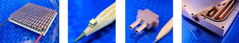
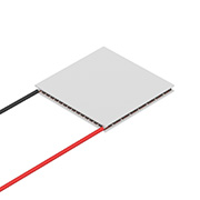 Thermoelectric Coolers (TECs)
 -
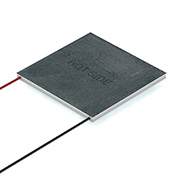 Thermoelectric Generators (TEGs)
 -
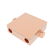
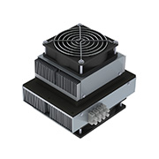 Thermoelectric Assemblies
 -
 Water Blocks / Liquid Cold Plates
 -
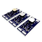 Electronics
 -
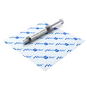 Thermal Interface Materials TIM
 -
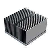 Accessories
 -
 Thermal Reference Sources


